
Background
I have a progressive hearing loss. Over the past 30 years, my hearing slowly
worsened until I became completely deaf. In 1989, I received a cochlear
implant, which consisted of a body-worn speech processor and a surgically
implanted receiver/stimulator which includes an electrode array placed
within the snail-shaped cochlea, deep in the skull. In a nutshell, a
microphone on my earpiece picks up sound, the processor analyzes,
digitizes and encodes it into an RF signal which is passed through the
skin to the implanted receiver. The electrode array is energized,
directly stimulating the auditory nerve, and sound is perceived.
It works pretty good. It sure beats being deaf, but I never felt
that I was getting the maximum benefit out of it: My speech recognition
was sporadic and I was unable to use the phone. High pitched sounds
caused a fierce itch. I became convinced that my Map (as the EEPROM
settings are called) was wrong but I was unable to find the magical
‘right’ setting with the re-mapper in my audiologist’s office.
Now suppose your TV set gave you greenish flesh tones. And to adjust the
color, you must first traverse a menu system, then adjust a flashing
all-red screen with a knob. Then a green one. Then a blue one. Back to
the menu. Wait a moment while the EEPROM is updated. Now back to the
picture, which now has purple flesh tones. Repeat until you are
blue in the face. This is the visual equivalent of how the audiologist’s
re-mapping program works. I figured there had to be a better way,
and I set out to find it.
I wanted to adjust my Map while listening to the effects of my tweaks.
I envisioned intercepting the RF signal which is normally applied to
the side of my head, post-processing it in real time using an ergonomic
graphical-equalizer type of interface, re-constructing a modified RF
data stream and (gulp) applying it to the side of my head.
My goal was to fix my own hearing.
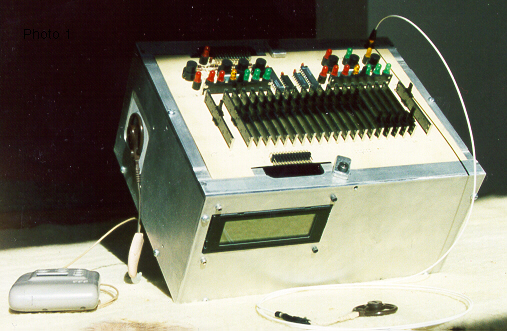
Photo 1 shows my Spectra Post Processor. SPP for short.
Reverse Engineering
Pretty far-fetched.
Obviously, my implant’s manufacturer was not going to FAX me details
of its encoding strategy. And asking my audiologist for help is a
stretch. If this is going to work, then a little reverse engineering
is in order.
From advertising blurbs and the owner’s manual, I know that the implanted electrode array has 22 electrodes, which are activated in dipole pairs 2 apart, for a total of 20 pairs. And that each pair is mapped to a band in the audio spectrum.
I also know that the strength of stimulation is a function of both the
level and duration of the selected dipole’s field.
Armed with these tidbits, I took a sine wave generator and hooked it up to
some wires wrapped around
a toilet paper tube, which conveniently fit snugly around my processor’s
telecoil attachment. This provided a stable audio frequency source of
magnetic ‘sound’ at the input end. At the output end, which normally connects
to my head, I rigged up a few turns of wire to ‘pick up’ whatever gets
beamed into my head and brought it up on an oscilloscope.

After a little head scratching, the RF encoding strategy became apparent.
Every 4 mS, my body-worn speech processor does a spectral analysis of
the sound it receives. Twenty frequency bands (corresponding to the 20
implanted electrode pairs) are considered. Up to 10 of the ‘noisiest’ bands
are encoded into RF and sent to the implanted array in my head.
Figure 2 shows the data stream when 3 electrode pairs are being fired
every 4 mS. Figure 3 blows up a single ‘frame’.


You can see that a frame consists
of 6 bursts, and the width of each burst in the frame tells the electronics
implanted in my head something specific about how to fire an electrode pair.
Apparently,
- Pulse 1 is a start bit
- Pulse 2 selects an electrode pair
- Pulse 3 is a mystery: nothing I could do changed it’s width.
- Pulses 4-6, in combination, determine the strength of stimulation
of the electrode pair.
So if I am going to capture, post-process, and re-generate this data stream
in real time, I have to
- Collect a full frame of data (300 uS)
- Analyze and modify it in software (??? uS)
- Transmit the modified frame (300 uS) and
- Repeat at the 400 uS frame rate.
This was not going to be simple.
The Hardware
The Big Picture
The SPP runs on a single 5V supply, and (ahem) draws way too much current
to run on batteries. All parts are stock items at Radio Shack or Digi-Key.
The console board was made with toner transfer. Everything else was
wire-wrapped onto standard 100 mil grid boards. My home-built aluminum
enclosure adds an attractive rustic look.
Figure 4 shows a block diagram of the SPP hardware.

The signal from my processor, which is normally applied to my head,
is picked up by a coil and fed to the Front End. This is a bunch of discrete
logic which converts the pulse widths and spaces to 9-bit entries in a FIFO.
This way, when the processor ‘downstream’ is ready for the next frame, it
needs only to clock in 12 numbers (6 widths and 6 spaces) from the Front End,
rather than spending a full 300 uS capturing one.
An 8-bit wide parallel bus connects the Front End with the Master controller
and a second FIFO. For debugging purposes, it also goes to the Slave
controller and to a PC via a parallel port interface. The Master controls
who drives data onto this bus using a ‘138 3:8 demuxer. For bi-directional
transfers from the PC or the Slave, a 2-wire handshake protocol is used.
Three controllers work together to get the job done:
The Master is a PIC 17C44. Its main function is to convert frames imported
from the Front End using rules determined by the graphical equalizer console.
Finished frames are exported, 12 bytes at a time, toward a second FIFO.
This keeps the Master very busy, but in its spare time, it controls the
parallel bus and monitors activity from the asynch and printer ports.
The ‘C44 was chosen because I rrreally needed a 1-cycle 8-bit multiply
instruction.
The Slave controller is a PIC 17C42. It performs the reverse function of
the Front End: It imports ‘finished’ frames from the 2nd FIFO and converts
them back to time-domain frames which can be pumped back into my head.
This task inherently takes at least 300 uS per frame. At 1 frame every
400 uS, there is little time for diversions.
The ‘C42 was chosen because it uses the same instruction set as the ‘C44.
The Operator Interface controller (OI for short) is a PIC 16C74. It monitors
the buttons and slider pots on the console panel and supports a menu system
on the LCD module. It talks to the Master using the PIC’s built-in
asynch module. The ‘C74 was chosen because of its A/D capability and
because it had plenty of IO pins.
PICs are probably not the best choice of controller family for this project.
In particular, using 8-bit controllers with 9-bit data added to the challenge.
But going into this project, I had zero experience with embedded controllers
and didn’t really expect to succeed, so cheap and simple were priorities.
The Front End
Each pulse in the RF data stream, it turns out, is built of a 2.56 MHz carrier.
Since the pulse
widths (and spaces) are too short to measure accurately with software or PIC
timers, I decided to measure them by counting the tics in the carrier.
Photo 2 and figure 5 show my ‘Front End’ board, which I built
with discrete logic. Its purpose is to convert the RF data stream into
a stream of 9-bit counts in a 64-entry FIFO.


The signal is picked up with a coil and fed to an LM306, which converts
each carrier cycle to a 200 nS TTL pulse. This goes to a Serial-In-Parallel-Out
shift register clocked at 20.48 MHz, which is 8x the carrier frequency.
Some random logic on the SIPO outputs extracts features like ‘Rising Edge’,
‘Missing Pulse’, etc. These signals are Registered to eliminate blips.
A pair of 8-bit counters counts the number of consecutive Missing Pulses,
and an overflow generates a timeout signal, which I use to recognize an
inter-frame space.
Two more counters measure the pulse widths and spaces. They are reset with
the ‘First Rising Edge’ or ‘First Missing Pulse’ signals and incremented
with the ‘Rising Edge’ or ‘Missing Pulse’ signals. Some extra logic captures
the overflow bits to supply that pesky 9th bit.

These widths and spaces are alternately clocked into the FIFO. The Master
controller, when it gets around to it, clocks an entry out of the FIFO
in 2 8-bit transactions (9 data bits + 4 status bits) over the parallel bus.
When the Master gets sidetracked talking to the PC or the Console, the FIFO
tends to overflow, so reset/re-arm capability is supplied.

The Controller Board
The main controller board is shown in Photo 3 and figures 10 and 11.
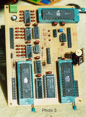

It holds the 3 PICs, an analog MUX, the output daughterboard, various
headers, and some extra logic.
Upon Reset, the Master initializes itself and then resets the Slave and the OI
controllers. An “Are you awake? Yup” conversation ensures that all systems are
go.
Each controller dedicates 4 lines to a bank of diagnostic LEDs. A crude
but effective flashing scheme gives the illusion that a full 8-bits is
being displayed.
The OI and the Master are clocked at 16 MHz. They communicate at 9600 baud
over a 2-wire asynch link. For wakeup and debugging purposes only, the
Master and Slave converse over the parallel bus using a 2-wire handshake.
The standard data path for Frame data comes from the Front End over the
parallel bus into the Master, where it is crunched. The Master then clocks
it back onto the bus and into the 9-bit register, and then into the FIFO.
The slave clocks it out of the FIFO on dedicated lines and generates a
gating signal to the output daughter-board.
The Slave is clocked at 10.24 MHz, so its XOUT pin comes out at 2.56 MHz.
This, you will recall, is the frequency of the original RF carrier.
The daughterboard combines the GATE with the XOUT and couples the result
into a resonant LC network, where the inductor is a 9-turn coil
which I duct-tape to the side of my head. The voltage across the coil
is a surprising 40 volts, and getting it to that level gave me as much
trouble as anything about this entire project.
The OI controller monitors the operator interface console. Two MODE buttons
put the system in ECHO or MODIFY mode, and the OI simply instructs the Master
which mode to operate in. In ECHO mode, the frame is passed unchanged, while
modify mode enables all the console settings.
The APPLY button instructs the OI to read all 24
slider POT values, which it does using a 24:3 analog mux, and ship the readings
to the Master over the asynch link. Two of the readings (the
Shift Amount and the Q-factor) are decoded into 1-of-7 settings which
are displayed with LEDs on the console. The shift setting lets me shift
electrode activity up to 3 pairs in either direction, changing the
perceived pitch of the sound. The Q-factor setting controls the rate
at which soft sounds become loud. The OI also drives a 4-line LCD
module and its 3-button menu traversal interface.
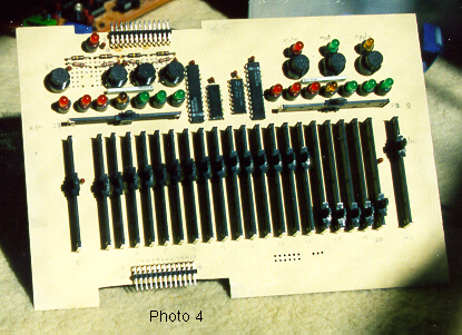
The Console is shown in photo 4 and figure 12.
Schematics for the Console, the Printer Port Interface, and other minor
circuits are supplied, but I won’t discuss them here.
The Software
All told, there are nearly 13000 lines of C and ASM in the SPP.
Copies of all source files are included on diskette.
They are:
- MASTER.ASM
The main source file for the Master controller. - SLAVE.ASM
The main source file for the Slave controller. - OI.ASM
The main source file for the OI controller. - FEFIFOH.ASM
This source is #included in master.asm. It contains the Front End FIFO
Handler. - QLUT.ASM
This source is #included in master.asm. It performs an adjustment of the
electrode stimulus level based on the Q-factor setting. It uses lookup
tables found in QLUTS.inc - EXDELAY.ASM
This source is #included in slave.asm. It contains code which lets
the Slave delay for an EXACT number of cycles. - OILCD.ASM
This source is #included in oi.asm. It contains code to drive the
LCD module. - OIMACS.ASM
This source is #included in oi.asm. It contains LCD-related macros. - OIMSGS.ASM
This source is #included in oi.asm. It contains LCD message strings. - OITOI.ASM
This source is #included in oi.asm. It handles the Threshold adjustment menu subsystem. - MASTER.INC
This include file defines values used in the Master source - SLAVE.INC
This include file defines values used in the Slave source. - OI.INC
This include file defines values used in the OI source. - SHARED.INC
This include file defines values shared by all ASM and C programs. - GOODIES.INC
This include file defines some convenient goodies. - DIVLUTS.INC
Contains lookup tables for a FAST (and pretty darned accurate) 8 bit
divide. - QLUTS.INC
Contains lookup tables used in QLUT.ASM. - SPP.C
A PC C program which talks to the SPP through the parallel printer port.
The functions it performs are for debugging. - DIVLUT.C
A C program used to generate the lookup tables in DIVLUTS.INC. - QLUT.C
A C program used to generate the lookup tables in QLUTS.INC.
All assembler programs were burned in on a PRO-MATE and debugged with the
time-tested crash & burn method. The diagnostic LED banks on each processor
allowed for display of error codes, and additional capabilities were
implemented via the printer port link to my PC.
All PC-to-SPP and OI-to-Master conversations followed this protocol:
- Sender sends a single command byte and waits for a response.
- When the receiver replies, both sides assume that it has the un-divided
attention of the other, so multi-byte transfers are allowed.Response consists of: 1 byte telling how many data bytes follow.
Followed by the data bytes. - Conversation goes back and forth until one side sends a 0-length
response, signifying end-of-message.
The Master Controller
The software for the Master controller is pretty complicated. The Master’s
main task is to shift a frame in from the Front End, modify it, and shift
it out toward the slave. Because of
the high data rate from the Front End and the complexity of the frame
modification algorithm, I moved heaven and earth to make this code fly.
It centers on a circular polling loop which gives priority to servicing
data from the Front End. Only when the Front End FIFO is empty does it
check for or respond to requests from the OI (via the asynch lines) or
the PC or the Slave (via their respective handshake lines). And whenever
it finishes responding to one of these peripheral tasks, it assumes
that the Front End FIFO has overflowed and that any partially accumulated
frames are corrupted and discards it.
When a FIFO entry is available, the Master shifts it in and performs
as much sanity checking on the partially accumulated frame as possible.
On the 12th entry, a full frame has been accumulated, and it modifies
the frame counts according to the rules set out by the POT settings on
the console.
I’d love to explain my frame modification algorithm, but it’s pretty
complicated. Here is the concept:
The stimulation level for a given electrode pair falls between the
“Threshold level” and the “Comfort level”. These min and max values
are burned into my body-worn processor’s EEPROM during a Mapping
session at my Audiologist’s office. The Threshold level is the
quietest level I can detect. The Comfort level is the loudest level
I can comfortably stand to hear. Using the slider POTs on the Console,
I want to re-map the incoming stimulus level to a different loudness.
Possibly even to a different electrode pair. In doing so, the widths
of up to 4 of the 6 pulses in the frame will need to be modified. The program flow
is summarized in figure 13. You can see that
there is a lot of arithmetic involved, including several table lookups,
a multiply, and a divide. It was not a trivial challenge to get
it all done, along with the import, export and sanity
checking, in the 400 uS available.
The Slave Controller
The Slave controller is utterly fixated on precise (+/- 200 nS) pulse
width control. The timings generated by the Slave’s gating signal
are going directly to my head, so it had better be right.
The software is based on a circular polling loop which, like the Master,
gives priority to servicing data from the 2nd FIFO.
It accumulates and sanity checks a 12-count frame and then goes
into Regen mode, in which it converts the counts into a precisely timed
gating signal. To make
a long story short, the Slave goes out of its way to achieve perfect
pulse width control all the way from the 3 uS start bit to the long 130-odd
uS spaces. It was harder than it sounds.
The OI Controller
The OI controller is not terribly busy. It spends most of its time idling
in a polling loop in which it checks for and responds to button presses
and activity on the asynch lines. It supports a menu system on the LCD
module using a 3-button system consisting of “Next Menu”, “Next Line”
and “Select”. When it has to read the slider POT values, it does so by
controlling the 24:3 analog MUX with 4 control lines, and uses an A/D
capture algorithm which is “straight out of the book”.
Although the OI program was a challenge to write and debug, it is positively
mechanical compared to the algorithms used in the Master and the Slave.
I won’t bore you with more details.
How It Turned Out
Better than I expected, but not as well as I’d hoped.
Better than I expected, because it works. It performs real-time post-
processing of the signal from my body-worn processor and re-generates
an improved signal which I was able to apply directly to my head.
It does electrode shifting, Q-factor adjustment, provides a threshold-
setting interface and by-electrode and ganged volume controls.
In addition, it’s a fine looking piece of equipment.
Not as well as I’d hoped, though, because even with all this functionality,
I was unable to improve my hearing enough to be able to use the
telephone. Apparently, the problem is not some magical tweak to my Map
after all. You can’t say I didn’t try.
My SPP is a home-brewed technical marvel. But also a
foolhardy undertaking. Lets face it: electrically stimulating an implanted
device is un-wise. In my own defense:
- I didn’t really expect to get it working.
- I was very careful.
- I rrreally wanted to improve my hearing.
And if my doctor couldn’t do it, I figured I ought to try.
Postscript
After finishing this project, I didn’t want to just give up.
I turned to the medical library and located papers in which my symptoms
(tactile sensations from high frequencies, etc) were attributed to
a mis-placed or extruded electrode array. After more than one attempt, I
convinced my doctors that my X-rays did, indeed, show that this was my problem.
In 1997, my old implant was removed and a new model was installed.
My itching sensations are gone, and I am again climbing the learning
curve with my new hearing.
My new body-worn processor uses an encoding strategy which is incompatible
with my SPP. This is just as well because sooner or later, I would have
made a coding error and fried my brain.
Is there an SPP/2 in my future? No Way.